Patent
| Title of the invention | Ultrasonic flaw-detection method and flaw detector |
|---|---|
| Patent number | No. 4672441 |
| Registration date | January 28, 2011 |
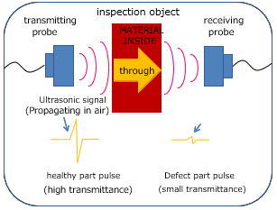
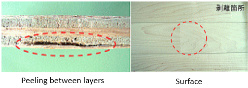
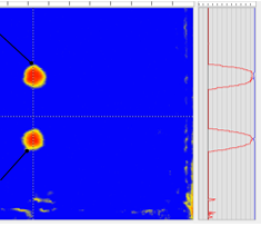
●The phase of reflected normal incident wave
The phase of the reflective wave is depending on the sign (plus or minus) of reflectivity obtained by the acoustic impedance of ultrasonic propagating medium and reflector.
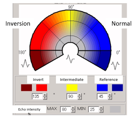
●The setting of color display by the phase of echo
This is the setting that display the ratio of waveform in a θ coordinate (polar coordinate) using color charts, which based on a forward waveform of a probe used in the test.
It can be discriminated what kind of reflector with accuracy by the color of the phase of reflected wave.
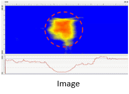
The setting of color display by the phase of echo
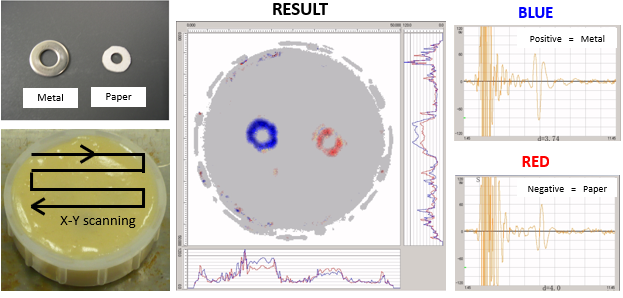
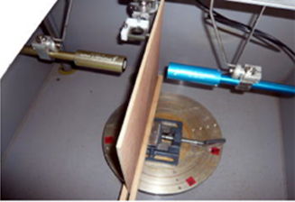
We scanned an epoxy resin test piece containing a piece of metal and paper by X-Y scanning.
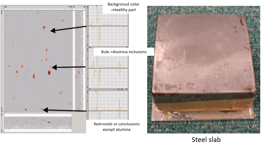
The phase of the reflected wave from Alumina containing steel is generally inversion, but it changes to normal inversion at the test using a spherical probe which has an adequate angle of incidence, and it can be discriminated between Alumina and void.
| Title of the invention | The method of a matrix crack detection in a CFRP laminate |
|---|---|
| Patent number | No. 4583550 |
| Registration date | September 10, 2010 |
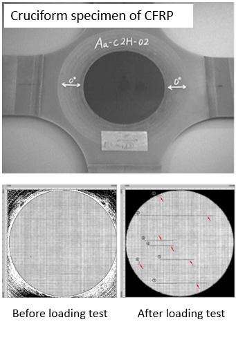
The testing of cruciform specimen
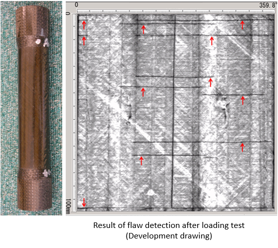
The testing of cylindrical specimen
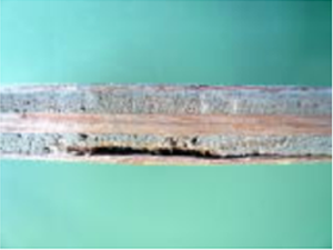
・What is Matrix crack?
A matrix crack, also known as a transverse crack, is an internal defect of a laminate sheet which runs vertically or horizontally along the surface of medium layer which constitutes a laminate sheet.The defects are progressed by transverse crack and delamination alternately.
・Detecting method
- 1、The conventionally method injects a contrast medium into the laminate sheet used as a test sample, applies X-ray, and looks at the shade.
- 2、There is a problem that they need the end face for injecting a contrast medium, cannot test the sample which has no end face like a tank or a container.
- 3、This method is able to verify the presence or absence of cracks by comparison of testing results, before and after fatigue test.